DC motors are continuous actuators that convert electrical energy into mechanical energy. DC motors achieve this by generating continuous angular rotation, which can be used to rotate pumps, fans, compressors, wheels, etc.
Like traditional rotating DC motors, linear motors can also be used, which can produce continuous bushing movement. There are basically three types of conventional motors available: AC motor, DC motor and stepping motor.
AC motors are usually used in high-power single-phase or multi-phase industrial applications. Constant rotating torque and speed are required to control large loads, such as fans or pumps.
In this tutorial, we only introduce simple lightweight DC motors and stepping motors, which are used in many different types of electronic, position control, microprocessor, PIC and robot circuits.
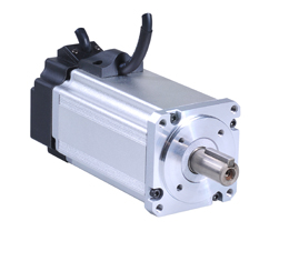
Basic DC motor the DC motor or DC motor, to give it a complete title, is used to produce continuous motion and rotation, and its speed can be easily controlled, so that they are suitable for application. It is the most commonly used actuator of speed control, servo control type, and / or positioning. DC motor consists of two parts, "stator" is the fixed part and "rotor" is the rotating part. As a result, basically three types of DC motors can be used.
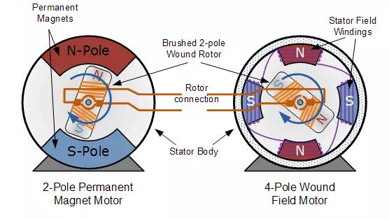
Brush motor – this type of motor generates a magnetic field in the wound rotor (rotating parts) by passing current through the commutator and brush assembly, so it is called "brush". The magnetic field of the stator (stationary part) is generated by using wound stator excitation winding or permanent magnet.
Generally, brushless DC motors are cheap, small and easy to control.
Brushless motor – this motor generates a magnetic field in the rotor by using a permanent magnet attached to it and reverses the direction electronically. They are usually smaller than conventional brush DC motors, but the price is higher because they use "Hall effect" switches in the stator to produce the required stator field rotation sequence, but they have better torque / speed characteristics, higher efficiency and longer service life than the same wire drawing type.
Servo motor – this motor is basically a brush DC motor with some form of position feedback control connected to the rotor shaft. They are connected to and controlled by PWM controller and are mainly used for position control system and radio control model.
Ordinary DC motor has almost linear characteristics, its rotation speed depends on the applied DC voltage, and the output torque depends on the current flowing through the motor winding. The rotation speed of any DC motor can range from a few revolutions per minute (RPM) to thousands of revolutions per minute, making it suitable for electronic, automotive or robot applications. By connecting them to the gearbox or gear train, their output speed can be reduced and the high-speed torque output of the motor can be improved.
"Brush" DC motor the traditional brush DC motor is basically composed of two parts. The static main body of the motor is called the stator, and the motion generated by internal rotation is called the rotor or "armature" of the DC motor.
The motor wound stator is an electromagnetic circuit, which is composed of circular wire coils connected together to produce the required rotating fixed magnetic field system of North Pole, South Pole and then north pole, which is different from AC motor. The stator magnetic field rotates continuously at the applied frequency. The current flowing in these excitation coils is called motor excitation current.
These electromagnetic coils forming the stator magnetic field can be connected in series, parallel or simultaneously with the motor armature (composite). The stator excitation winding of the series wound DC motor is connected in series with the armature. Similarly, the stator excitation winding of parallel winding DC motor is connected in parallel with the armature, as shown in the figure.
Series and parallel DC motors
The rotor or armature of a DC motor consists of a current carrying conductor, one end of which is connected to an electrically isolated copper section called a commutator. The commutator allows an electrical connection to an external power source through a carbon brush (therefore called a "brush" motor) when the armature rotates.
The magnetic field established by the rotor attempts to align itself with the stationary stator magnetic field, resulting in the rotor rotating along its axis, but it cannot align itself due to the commutation delay. The speed of the motor depends on the strength of the rotor magnetic field. The greater the voltage applied to the motor, the faster the rotor rotates. The speed of the motor can also be changed by changing the applied DC voltage.
Conventional (brush) DC motor
Permanent magnet (PMDC) brushless DC motors are usually much smaller and cheaper than equivalent wound stator DC motors because they have no excitation windings. In permanent magnet direct current (PMDC) motors, these excitation coils are replaced by strong rare earth (such as cobolt or NdFeB) magnets with high magnetic field energy.
The use of permanent magnet makes the linear speed / torque characteristic of DC motor much better than that of equivalent wound motor, because it has permanent magnetic field (sometimes very strong magnetic field), which makes it more suitable for models, robots and servo systems.
Although the DC brush motor is very efficient and cheap, the problem related to the DC brush motor is that under heavy load conditions, sparks will be generated between the two surfaces of the commutator and the carbon brush, resulting in self heating, short life and electrical noise due to sparks, which will damage any semiconductor switching device, such as MOSFET or transistor. In order to overcome these shortcomings, a brushless DC motor is developed.
"Brushless" DC motor brushless DC motor (BDCM) is very similar to permanent magnet DC motor, but no brush can be replaced or worn due to commutator spark. Therefore, little heat is generated in the rotor, thus prolonging the service life of the motor. The design of brushless motor eliminates the need for brushes by using more complex drive circuits, because the rotor magnetic field is a permanent magnet, which is always synchronized with the stator magnetic field, so that more accurate speed and torque control can be realized.
Then, the structure of Brushless DC motor is very similar to AC motor, so it becomes a real synchronous motor, but the disadvantage is that it is more expensive than the equivalent "brush" motor design.
The control method of Brushless DC motor is very different from that of ordinary brushless DC motor, because it can detect the rotor angular position (or magnetic pole) required to generate the feedback signal required to control the semiconductor switch in combination with some control methods of Brushless DC motor. Equipment. The most common position / pole sensor is the "Hall effect sensor", but some motors also use optical sensors.
Using Hall effect sensor, the polarity of electromagnet is switched by motor control drive circuit. The motor can then be easily synchronized with the digital clock signal to provide accurate speed control. The brushless DC motor may be configured to have an external permanent magnet rotor and an internal electromagnetic stator, or an internal permanent magnet rotor and an external electromagnetic stator.
Compared with "brush" cousin, brushless DC motor has the advantages of higher efficiency, higher reliability, lower electrical noise, good speed control and, more importantly, higher speed without brush or commutator. However, their disadvantage is that they are more expensive and more complex to control.
DC servo motor DC servo motor is used in closed-loop applications to feed back the position of the output motor shaft to the motor control circuit. Typical position "feedback" devices include resolvers, encoders, and potentiometers for radio control models such as aircraft and ships.
Servo motors usually include a built-in gearbox for deceleration and can directly transmit high torque. Due to the installation of gearbox and feedback device, the output shaft of servo motor cannot rotate freely like the shaft of DC motor.
Block diagram of DC servo motor

The servo motor consists of DC motor, reduction gearbox, position feedback device and some form of error correction. The speed or position is controlled relative to the position input signal or reference signal applied to the device.
Servo motor
The error detection amplifier will view this input signal and compare it with the feedback signal from the motor output shaft to determine whether the motor output shaft is in an error state. If so, the controller will make appropriate correction to accelerate or decelerate the motor. This response to the position feedback device means that the servo motor operates in a "closed-loop system".
In addition to large industrial applications, servo motors are also used in small remote control models and robotics. Most servo motors can rotate about 180 degrees in both directions, so they are very suitable for accurate angle positioning. However, unless specially modified, these RC servers cannot rotate continuously at high speed like traditional DC motors.
The servo motor consists of multiple devices in one device, motor, gearbox, feedback device and error correction for controlling position, direction or speed. They can be easily controlled by using only three wires of power supply, grounding and signal control, so they are widely used in robots and small models.
DC motor switch and control small DC motors can be "on" or "off" through switches, relays, transistors or MOSFET circuits. The simplest form of motor control is "linear" control. This type of circuit uses bipolar transistors as switches (Darlington transistors can also be used if higher rated current is required) to control the motor from a single power supply.
DC motors are continuous actuators that convert electrical energy into mechanical energy. DC motors achieve this by generating continuous angular rotation, which can be used to rotate pumps, fans, compressors, wheels, etc.
Like traditional rotating DC motors, linear motors can also be used, which can produce continuous bushing movement. There are basically three types of conventional motors available: AC motor, DC motor and stepping motor.
AC motors are usually used in high-power single-phase or multi-phase industrial applications. Constant rotating torque and speed are required to control large loads, such as fans or pumps.
In this tutorial, we only introduce simple lightweight DC motors and stepping motors, which are used in many different types of electronic, position control, microprocessor, PIC and robot circuits.
Basic DC motor the DC motor or DC motor, to give it a complete title, is used to produce continuous motion and rotation, and its speed can be easily controlled, so that they are suitable for application. It is the most commonly used actuator of speed control, servo control type, and / or positioning. DC motor consists of two parts, "stator" is the fixed part and "rotor" is the rotating part. As a result, basically three types of DC motors can be used.
Brush motor – this type of motor generates a magnetic field in the wound rotor (rotating parts) by passing current through the commutator and brush assembly, so it is called "brush". The magnetic field of the stator (stationary part) is generated by using wound stator excitation winding or permanent magnet. Generally, brushless DC motors are cheap, small and easy to control.
Brushless motor – this motor generates a magnetic field in the rotor by using a permanent magnet attached to it and reverses the direction electronically. They are usually smaller than conventional brush DC motors, but the price is higher because they use "Hall effect" switches in the stator to produce the required stator field rotation sequence, but they have better torque / speed characteristics, higher efficiency and longer service life than the same wire drawing type.
Servo motor – this motor is basically a brush DC motor with some form of position feedback control connected to the rotor shaft. They are connected to and controlled by PWM controller and are mainly used for position control system and radio control model.
Ordinary DC motor has almost linear characteristics, its rotation speed depends on the applied DC voltage, and the output torque depends on the current flowing through the motor winding. The rotation speed of any DC motor can range from a few revolutions per minute (RPM) to thousands of revolutions per minute, making it suitable for electronic, automotive or robot applications. By connecting them to the gearbox or gear train, their output speed can be reduced and the high-speed torque output of the motor can be improved.
"Brush" DC motor the traditional brush DC motor is basically composed of two parts. The static main body of the motor is called the stator, and the motion generated by internal rotation is called the rotor or "armature" of the DC motor.
The motor wound stator is an electromagnetic circuit, which is composed of circular wire coils connected together to produce the required rotating fixed magnetic field system of North Pole, South Pole and then north pole, which is different from AC motor. The stator magnetic field rotates continuously at the applied frequency. The current flowing in these excitation coils is called motor excitation current.
These electromagnetic coils forming the stator magnetic field can be connected in series, parallel or simultaneously with the motor armature (composite). The stator excitation winding of the series wound DC motor is connected in series with the armature. Similarly, the stator excitation winding of parallel winding DC motor is connected in parallel with the armature, as shown in the figure.
Series and parallel DC motors
The rotor or armature of a DC motor consists of a current carrying conductor, one end of which is connected to an electrically isolated copper section called a commutator. The commutator allows an electrical connection to an external power source through a carbon brush (therefore called a "brush" motor) when the armature rotates.
The magnetic field established by the rotor attempts to align itself with the stationary stator magnetic field, resulting in the rotor rotating along its axis, but it cannot align itself due to the commutation delay. The speed of the motor depends on the strength of the rotor magnetic field. The greater the voltage applied to the motor, the faster the rotor rotates. The speed of the motor can also be changed by changing the applied DC voltage.
Conventional (brush) DC motor
Permanent magnet (PMDC) brushless DC motors are usually much smaller and cheaper than equivalent wound stator DC motors because they have no excitation windings. In permanent magnet direct current (PMDC) motors, these excitation coils are replaced by strong rare earth (such as cobolt or NdFeB) magnets with high magnetic field energy.
The use of permanent magnet makes the linear speed / torque characteristic of DC motor much better than that of equivalent wound motor, because it has permanent magnetic field (sometimes very strong magnetic field), which makes it more suitable for models, robots and servo systems.
Although the DC brush motor is very efficient and cheap, the problem related to the DC brush motor is that under heavy load conditions, sparks will be generated between the two surfaces of the commutator and the carbon brush, resulting in self heating, short life and electrical noise due to sparks, which will damage any semiconductor switching device, such as MOSFET or transistor. In order to overcome these shortcomings, a brushless DC motor is developed.
"Brushless" DC motor brushless DC motor (BDCM) is very similar to permanent magnet DC motor, but no brush can be replaced or worn due to commutator spark. Therefore, little heat is generated in the rotor, thus prolonging the service life of the motor. The design of brushless motor eliminates the need for brushes by using more complex drive circuits, because the rotor magnetic field is a permanent magnet, which is always synchronized with the stator magnetic field, so that more accurate speed and torque control can be realized.
Then, the structure of Brushless DC motor is very similar to AC motor, so it becomes a real synchronous motor, but the disadvantage is that it is more expensive than the equivalent "brush" motor design.
The control method of Brushless DC motor is very different from that of ordinary brushless DC motor, because it can detect the rotor angular position (or magnetic pole) required to generate the feedback signal required to control the semiconductor switch in combination with some control methods of Brushless DC motor. Equipment. The most common position / pole sensor is the "Hall effect sensor", but some motors also use optical sensors.
Using Hall effect sensor, the polarity of electromagnet is switched by motor control drive circuit. The motor can then be easily synchronized with the digital clock signal to provide accurate speed control. The brushless DC motor may be configured to have an external permanent magnet rotor and an internal electromagnetic stator, or an internal permanent magnet rotor and an external electromagnetic stator.
Compared with "brush" cousin, brushless DC motor has the advantages of higher efficiency, higher reliability, lower electrical noise, good speed control and, more importantly, higher speed without brush or commutator. However, their disadvantage is that they are more expensive and more complex to control.
DC servo motor DC servo motor is used in closed-loop applications to feed back the position of the output motor shaft to the motor control circuit. Typical position "feedback" devices include resolvers, encoders, and potentiometers for radio control models such as aircraft and ships.
Servo motors usually include a built-in gearbox for deceleration and can directly transmit high torque. Due to the installation of gearbox and feedback device, the output shaft of servo motor cannot rotate freely like the shaft of DC motor.
Block diagram of DC servo motor
The servo motor consists of DC motor, reduction gearbox, position feedback device and some form of error correction. The speed or position is controlled relative to the position input signal or reference signal applied to the device.
Servo motor
The error detection amplifier will view this input signal and compare it with the feedback signal from the motor output shaft to determine whether the motor output shaft is in an error state. If so, the controller will make appropriate correction to accelerate or decelerate the motor. This response to the position feedback device means that the servo motor operates in a "closed-loop system".
In addition to large industrial applications, servo motors are also used in small remote control models and robotics. Most servo motors can rotate about 180 degrees in both directions, so they are very suitable for accurate angle positioning. However, unless specially modified, these RC servers cannot rotate continuously at high speed like traditional DC motors.
The servo motor consists of multiple devices in one device, motor, gearbox, feedback device and error correction for controlling position, direction or speed. They can be easily controlled by using only three wires of power supply, grounding and signal control, so they are widely used in robots and small models.
DC motor switch and control small DC motors can be "on" or "off" through switches, relays, transistors or MOSFET circuits. The simplest form of motor control is "linear" control. This type of circuit uses bipolar transistors as switches (Darlington transistors can also be used if higher rated current is required) to control the motor from a single power supply.
By changing the amount of base current flowing into the transistor, the speed of the motor can be controlled. For example, if the transistor is "half way" on, only half of the power supply voltage flows to the motor. If the transistor is "fully on" (saturated), all supply voltage flows to the motor and rotates faster. Then, for this type of linear control, the power will be continuously transmitted to the motor, as shown below.
Motor speed control
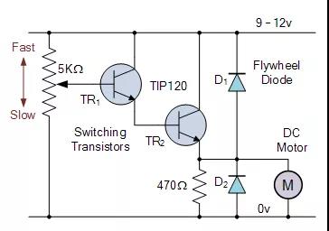
The simple switching circuit above shows the circuit of the speed control circuit of the unidirectional (only one direction) motor. Because the speed of DC motor is directly proportional to the voltage at both ends, we can use transistors to adjust the voltage at this end.
Two transistors are connected as Darlington pairs to control the main armature current of the motor. A 5K Ω potentiometer is used to control the base driving amount to the first pilot transistor Tr 1, which in turn controls the main switching transistor, TR 2 allows the DC voltage of the motor to change from zero to VCC, in this embodiment 9 to 12 volts.
An optional flywheel diode is bridged between the switching transistor Tr 2 and the motor terminal to prevent back EMF generated when the motor rotates. The adjustable potentiometer can be replaced by a continuous logic "1" or logic "0" signal directly added to the circuit input to "fully open" (saturated) or "fully close" (cut off) the motor from the port of the microcontroller or pic, respectively.
In addition to the basic speed control, the same circuit can be used to control the speed of the motor. By repeatedly switching the motor currents "on" and "off" at a sufficiently high frequency, the speed of the motor can be changed between stationary (0 RPM) and full speed (100%) by changing its marking space ratio. Supply. This can be achieved by changing the ratio of the "on" time (t on) to the "off" time (t off), and can be achieved using a process called pulse width modulation.
Pulse width speed control as we said earlier, the speed of DC motor is directly proportional to the average (average) voltage value on its terminal, and the higher the value, the faster the motor rotates until the maximum allowable motor voltage is reached. In other words, the higher the voltage, the faster the speed. By changing the ratio between "on" time and "off" duration, called "duty cycle", "mark / spacing ratio" or "duty cycle", it can be concluded that the motor voltage and its speed can be changed. For simple unipolar drivers, the duty cycle β Is:
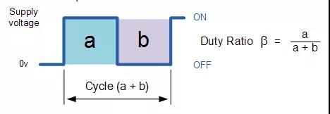
The average DC output voltage fed into the motor is: vmean= β x Vsupply。 Then, by changing the width of pulse a, the motor voltage can be controlled, so that the power applied to the motor can be controlled. This control method is called pulse width modulation or PWM.
Another way to control the motor speed is to change the frequency (and the time period of the control voltage) while keeping the "on" and "off" duty cycle time unchanged. This control is called pulse frequency modulation or PFM.
By pulse frequency modulation, the motor voltage is controlled by applying pulses of variable frequency. For example, with low frequency or few pulses, the average voltage applied to the motor is low, so the motor speed is slow. At higher frequencies or with many pulses, the average motor terminal voltage increases and the motor speed increases.
The transistor can then be used to control the power applied to the DC motor, and its operating mode is "linear" (motor voltage change), "pulse width modulation" (pulse width change), or "pulse frequency" modulation (change pulse frequency).
Reversing the direction of DC motor although using a single transistor to control the speed of DC motor has many advantages, it also has a main disadvantage, that is, the rotation direction is always the same, which is a "one-way" circuit. In many applications, we need to operate the motor in both positive and negative directions.
In order to control the direction of the DC motor, the polarity of the DC power supply applied to the motor connection must be reversed so that its axis rotates in the opposite direction.
A very simple and inexpensive way to control the direction of rotation of a DC motor is to use different switches arranged in the following manner:
DC motor direction control
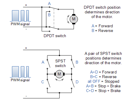
The first circuit uses a single double pole double throw (DPDT) switch to control the polarity of the motor connection. By switching the contact, the power supply of the motor terminal can be reversed and the direction of the motor can be reversed. The second circuit is slightly more complex and uses four single pole single throw (SPST) switches configured in an "H" shape.
The mechanical switches are arranged in pairs and must be operated in a specific combination to operate or stop the DC motor. For example, as shown in the figure, switch combination a + D controls forward rotation and switch B + C controls reverse rotation. The combination switch a + B or C + D shortens the motor terminal to make it brake quickly. However, using the switch in this way is dangerous because operating the switch a + C or B + D together will short circuit the power supply.
Although the above two circuits work well in most small DC motor applications, do we really want to operate different combinations of mechanical switches just to reverse the direction of the motor? We can change the manual switch of electromechanical relay group and have a single forward / backward button or switch, and even use solid-state CMOS 4066b four sided two-way switch.
However, another good way to realize bidirectional control of the motor (and its speed) is to connect the motor to the transistor H-bridge circuit device, as shown below.
Basic bidirectional H-bridge circuit
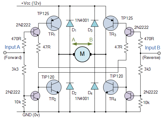
The upper part of the H-bridge circuit is so named because the four switches, whether electromechanical relays or transistors, are similar to the letter "H" and the basic structure of the motor located on the center bar. Transistor or MOSFET H-bridge may be one of the most commonly used types in bidirectional DC motor control circuits. It uses "complementary transistor pairs" of NPN and PNP in each branch, and the transistors are switched together in pairs to control the motor.
Control input a runs the motor in one direction (forward rotation) and input B runs the motor in the other direction (reverse rotation). Then, the direction control of the motor can be realized by switching the transistors in its "diagonal pair" to "on" or "off".
For example, when transistor Tr1 is "on" and transistor TR2 is "off", point a is connected to the power supply voltage (+ VCC), and if transistor TR3 is "off" and transistor TR4 is "on", point B is connected to 0 volts (GND). Then, the motor will rotate in a direction positive to motor terminal A and negative to motor terminal B.
If the switching state is reversed so that Tr1 is "off", TR2 is "on", TR3 is "on" and TR4 is "off", the motor current will flow in the opposite direction, so as to reverse the rotation direction of the motor.
Then, by applying the opposite logic level "1" or "0" to inputs a and B, the rotation direction of the motor can be controlled as follows.
H bridge truth table
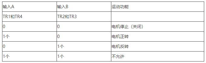
It is important that no other input combinations are allowed, as this may cause a short circuit in the power supply, i.e. both transistors Tr1 and TR2 are switched to "on" at the same time (fuse = explosion!).
Like the unidirectional DC motor control seen above, pulse width modulation or PWM can also be used to control the speed of the motor. Then, by combining the H-bridge switch with PWM control, the direction and speed of the motor can be accurately controlled.
Commercial off the shelf Decoder IC, such as sn754410 four channel half H-bridge IC or L298N with two H-bridges, can provide all necessary control and safety logic built-in. These logic and safety logic are specially designed for H-bridge bidirectional motor control circuit.
Like the DC motor above, the stepping motor is also an electromechanical actuator. It converts the pulse digital input signal into discrete (incremental) mechanical motion, which has been widely used in industrial control applications. Stepping motor is a kind of synchronous brushless motor. It does not have an armature with commutator and carbon brush, but a rotor composed of many rotors. Some types of rotors have hundreds of permanent magnet teeth and a stator with a single winding.
Stepper motor
As the name implies, the stepping motor will not rotate continuously like the conventional DC motor, but move in discrete "stepping" or "increment". The angle of each rotation or step depends on the number of stator poles and rotors and the teeth of the stepping motor.
Due to its discrete stepping operation, the stepping motor can easily rotate a limited part at a time, such as 1.8, 3.6, 7.5 degrees, etc. Therefore, for example, suppose that the stepper motor completes a full turn (360 o minutes and 100 steps).
Then, the step angle of the motor is 360 degrees / 100 steps = 3.6 degrees per step. This value is commonly referred to as the "stepping angle" of the stepper motor.
There are three basic types of stepper motors, variable reluctance, permanent magnet and hybrid (a combination of the two). A stepper motor is especially suitable for applications that require accurate positioning and repeatability to start, stop, reverse and speed control together with the fast response of another key feature of stepper motor. It is able to maintain the stability of load capacity once the required position is achieved.
Generally, a stepping motor has an internal rotor with a large number of permanent magnet "teeth", and a plurality of electromagnet "teeth" are installed on the stator. The stator electromagnet is polarized and depolarized in turn, so that the rotor rotates one "step" at a time.
Modern multipole, multi tooth stepper motors have a step accuracy of less than 0.9 degrees (400 pulses per revolution) and are mainly used in highly accurate positioning systems, such as magnetic head positioning systems in floppy disk / hard disk drives, printers / plotters or robot applications. The most commonly used stepper motor is a stepper motor with 200 steps per revolution. It has a 50 tooth rotor, 4-phase stator and 1.8 degrees (360 degrees / (50 × 4) Step angle of).
Structure and control of stepping motor
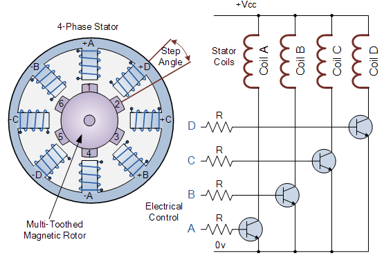
In the simple example of the variable reluctance stepping motor above, the motor consists of a central rotor surrounded by four electromagnetic field coils marked a, B, C and D. All coils with the same letter are connected together to energize, for example, a coil marked a will cause the magnetic rotor to align with the set of coils.
By supplying power to each group of coils in turn, the rotor can rotate or "step" an angle from one position, which is determined by its step angle structure, and the rotor will produce rotational motion by exciting the coils in turn.
The stepping motor driver controls the stepping angle and speed of the motor by energizing the excitation coil according to the setting sequence (e.g. "adcb, adcb, adcb, a..."), the rotor will rotate in one direction (forward), reverse the pulse sequence to "ABCD, ABCD, ABCD, a...", and the rotor will rotate in the opposite direction (reverse).
Therefore, in the simple example above, the stepper motor has four coils, making it a 4-phase motor, the number of poles on the stator is eight (2 x 4), and the spacing of each phase is 45 degrees. The number of teeth on the rotor is six, 60 degrees apart.
Then, the rotor has 24 possible positions (6 teeth x 4 coils) or "steps" to complete a full turn. Therefore, the above step angle is 360 O / 24 = 15 o.
Obviously, more rotor teeth and / or stator coils will lead to more control and smaller step angle. Similarly, by connecting the coils of the motor in different configurations, full step, half step and micro step angle can be realized. However, to realize micro stepping, the stepping motor must be driven by (quasi) sinusoidal current, which is very expensive.
The rotation speed of the stepping motor can also be controlled by changing the time delay (frequency) between the digital pulses applied to the coil. The longer the delay time, the slower the speed of a whole turn. By applying a fixed number of pulses to the motor, the motor shaft will rotate a given angle.
The advantage of using delay pulses is that no additional feedback in any form is required, because the final position of the rotor can be accurately known by counting the number of pulses supplied to the motor. This response to a certain number of digital input pulses makes the stepper motor run in an "open-loop system", which makes the control easy and cheap.
For example, suppose that the step angle of the stepping motor above is 3.6 degrees per step. To rotate the motor by an angle of 216 degrees, for example, and then stop at the desired position, a total of 216 degrees / (3.6 degrees / step) = 80 pulses are applied to the stator coil.
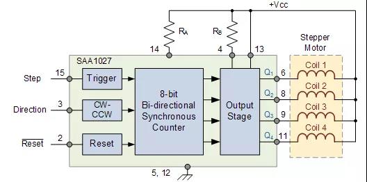
There are many stepper motor controller ICs available, which can control stepper speed, rotation speed and motor direction. SAA1027 is such a controller IC, which has built-in all necessary counter and code conversion functions, and can automatically drive four fully controlled bridge outputs to the motor in the correct order.
The direction of rotation can also be selected with single step mode or continuous (stepless) rotation in the selected direction, but this brings some burden to the controller. When an 8-bit digital controller is used, 256 microsteps can also be achieved in each step
SAA1027 stepper motor control chip
In this tutorial on rotary actuators, we studied brush and brushless DC motors, DC servo motors and stepping motors, which are electromechanical actuators that can be used as output devices for position or speed control.